

صفحه Instrument-Appendix
 |
|
 |
|
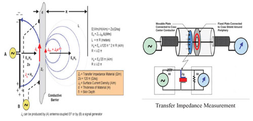
Shield Effectiveness
Transfer Impedance
|
|
|
Above Figure illustrates the relationship between the radiated and transfer impedance methods. In the radiated case (A), an antenna-coupled EF induces current into the RF gasket material. For transfer impedance measurements (B), a signal generator is used. The Zst is a complex quantity that combines the material’s DC surface resistance (Rs) and its surface inductive reactance (Xsl).
Transfer Impedance is defined as: Zt = ( 1 / I0 ) x ( dV / dx )
Conclusion : |
|
 |
|
Types of Noise and Their Effects on the cables
For transducer connection to the instrument , the cable transmits a very low e.m.f. signal. |
|
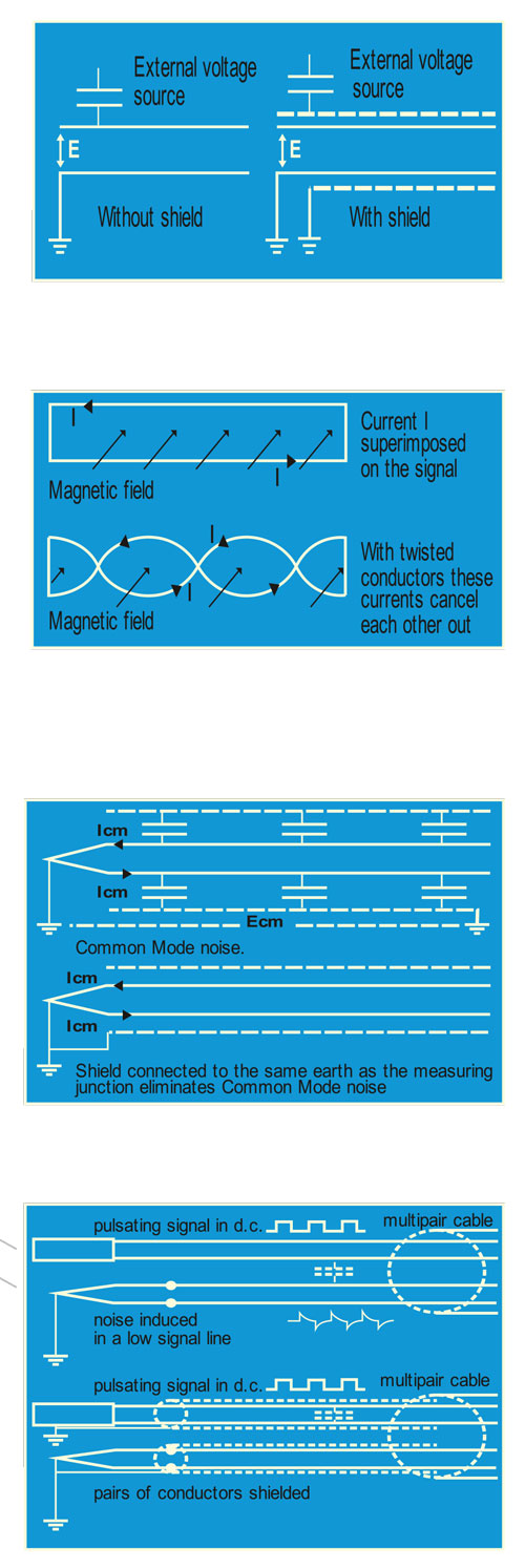 |
Static Noise
This is interference caused by coupling of capacity between external electrical field from power line or another voltage source and the cable. Interposing a single shield which forms a capacitor when connected to the earth.
|
Magnetic NoiseGenerally low frequency electromagnetic field due to power cable, motor, ctc. Can induce e.m.f. into the instrumentation cable. The twisting of conductors provides a good reduction of the magnetic noise. Other reduction are given by steel conduit, armours (high inductance material).Is some particular cases low resisting screen(i.e.copper braids, copper tapes) may be necessary. |
|
Common-Mode NoiseThis is typical interference caused when the instrumentation loop is earthed on two sides with different potential. To avoid this noise the shield, instrument or hot junction of thermocouple must be commonly earthed. |
|
Cross Talk NoiseThis is caused by unbalanced capacitance from adjacent cabling elements of different construction . To reduce this noise for pair/triad/quad cables, differing lay of twist is used or more effectively each pair/triad/quad is individually shielded (i.e. aluminium/polyester 100% coverage) and commonly earthed. |
|
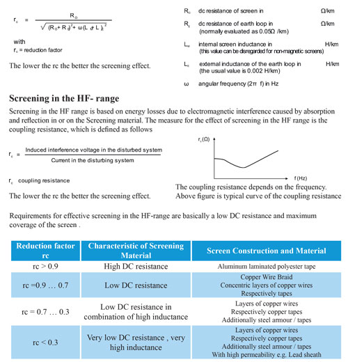
Reduction Factor of ScreenExternal interferenceScreening against external interference has to take the influence of both electric and magnetic interference into account and make a distinction between LF and HF fields.’The design of the required screen depends on the type and strength of interference Screening in the LF-range
For screening in the LF-range – i.e. in the range of frequencies of up to 10kHz – the influence of both electric and magnetic interference can be examined separately. Interference from electric fields can be virtually disregarded if conductive screens are used; the lower the dc resistance, the better the screening effect; however, care must be taken to ensure a high degree of coverage as the electric field may otherwise affect the cable core.Screening against LF magnetic interference requires the use of magnetic materials such as steel wires or(even better) tapes. Materials of high permeability should be used for high levels of screening.
|
|