

Page Telephone-A Summary of IEC 60708
|
A Summary of IEC 60708
Scope
1) Conductor |
|
|
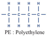
2) Insulation -Insulation material The conductor shall be covered with solid or cellular polyolefin insulation or any combination thereof. - (Polyethylene or Polypropylene) |
 |
|
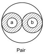
3)Cabling element A cabling element shall be – a pair of two insulated conductors twisted together and Designated wire a and wire b |
 |
|
4)Stranding The cable elements shall be formed into a number of sub-units or units which can be stranded into a regular make up to produce the required number of pairs. -25 pair count The pairs shall be identified by each insulated conductor having a single colour in accordance with the colour scheme given in Annex C. Sub-units shall be identified by coloured bindings of tape or threads. Each group of sub-units making up a 25 pair count shall be identified by a common colour of bindings. |
 |
|
5)Filling
6)Core protection |
|
|
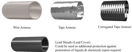
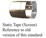
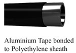
7)Sheath -General: A moisture barrier aluminium laminated polyethylene sheath construction is specified for both underground and aerial cables. This type of sheath will also provide screening. For aerial cables a figure “8” construction is specified. Circular sheath cables can also be used as aerial cables. -Sheath material : Aluminium Tape bonded to Polyethylene sheath . -Aluminium tape: The aluminium tape shall be coated on at least one side with a polymer film. The aluminium tape without the polymer layer shall have a nominal thickness of at least 0.15 mm. -Polyethylene: The polyethylene shall have a minimum carbon black content of 2.0 %. |
 |
|
8)Cable protection
|
|
|
A Summary of IEC 60708 (Electrical Requirements)
LOW-FREQUENCY CABLES WITH POLYOLEFIN INSULATION AND
MOISTURE BARRIER POLYOLEFIN SHEATH
|
|
|
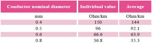
1) Electrical resistance of conductor
|
|
|
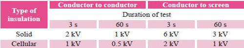
2) Dielectric strength
The dielectric strength of the insulation shall be checked on the finished cable.
The insulation shall withstand the application of a d.c. test voltage.
The test voltages for alternative durations are given in following table .
 |
|
|
3) Insulation resistance
The insulation resistance at a temperature of 20 °C shall be not less than:
- for filled cables 1 500 MOhm x km
- or unfilled cables 5000 MOhm x km
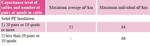
4) Mutual capacitance
The mutual capacitance shall not exceed the values given in following Table.
|
|
 |
|
|
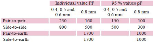
5) Capacitance unbalance
The capacitance unbalance shall not exceed the values given in following Table per 500 m length of cable:
|
|
 |
|
|
*** Following Parameters aren’t applicable to A-2Y(St)2Y cables with static screen.
6) Attenuation
Attenuation values depend on cable design and should be given by the manufacturer.
Measurement method according to IEC 61156-1, 3.3.2.
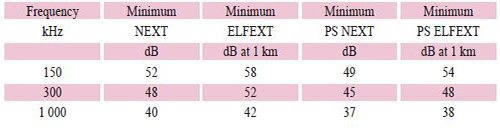
7) Near End Crosstalk (NEXT)
NEXT values are given in Table 6.
Measurement method according to IEC 61156-1, 3.3.3.
8) Equal Level Far-end Crosstalk (ELFEXT)
ELFEXT values are given in following Table.
Measurement method according to IEC 61156-1, 3.3.5.
9) Power sum (PS) of crosstalk loss
Power sum values of near-end and equal-level far-end crosstalk loss are given in following Table.
Measurement method according to IEC 61156-1
|
|
 |
|
|
10) Characteristic impedance
The nominal value of characteristic impedance Z0 of the cable shall be in the range from 80 Ohms to
130 Ohms at 1 MHz, depending on the design. The maximum deviation from the nominal characteristic
impedance shall be within ±15 %.
Measurement method according to IEC 61156-1, 3.3.6.
11) Velocity of propagation
The velocity of propagation shall be >60 % at 1 MHz.
Measurement method according to IEC 61156-1, 3.3.1.
|
|