|
A Summary of EN 50288-7 (2005)
Multi-element metallic cables used in analogue and digital communication and control
Part 7: Sectional specification for instrumentation and control cables
Scope :
This sectional specification covers multi-element cables suitable for connecting instruments and control systems for analogue or digital signal transmission.
They may or may not be screened and optionally may incorporate armouring and/or moisture or environmental protection layers.
The cables shall have a mechanically robust construction and electrical transmission handling properties.
The electrical, mechanical, transmission and environmental performance characteristics of the cables, related to their reference test methods are detailed .
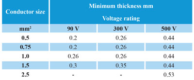
Cables covered by this specification have maximum rated voltages of 90 V, 300 V and 500 V a.c.
These cables shall not be connected directly to mains electricity supply or other low impedance sources.
Multi-element cables for use in analogue, digital and control circuits are not designed to be used for power supply.
1) Conductor
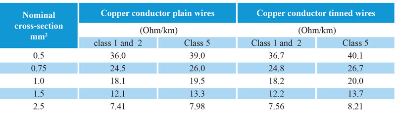
Conductors shall be solid, stranded or flexible plain or metal coated copper in accordance with Class 1, 2 or 5 of HD 383 ( equal to IEC 60228) in the range of 0.5 mm2 to 2.5 mm2 .
For multi-core cables the maximum conductor resistance shall be as HD 383 ( equal to IEC 60228) , and for finished multi-pair, multi- triple and multi-quad cables the maximum resistance of HD 383 shall be increased by 2 %.
Conductor joints shall be as EN 50288-1 (IEC 60228) .
Stranded and flexible conductors shall consist of wires circular in cross section assembled, without insulation between them, by concentric stranding or by bunching.
When the installed length of cable results in a high conductor resistance, larger conductor sizes can be used.
The values are extracted from DIN VDE 0295 (equivalent with the international standard IEC 60228 and HD 383), according to cross-sections and conductor classes, beginning with nominal cross-section of 0.5 mm2 .
|
 |
|
2 ) Insulation
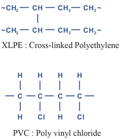
The insulating material shall be selected from those listed below.
a) PVC EN 50290-2-21
b) Polyethylene EN 50290-2-23
c) Polypropylene EN 50290-2-25
d) Halogen free F.R EN 50290-2-26
e) Cross-linked polyethylene EN 50290-2-29
|
 |
|
The minimum thickness at any point of the insulation shall not be less than the value given in following Table
|
 |
|
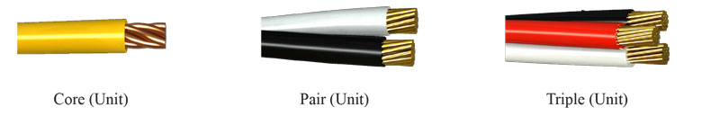
3 ) Cable elements
The cable element is:
a single insulated wire, or a pair consisting of two insulated conductors twisted together and designated wire “a” and wire “b”, or a triple consisting of three insulated conductors twisted together and designated wire “a”, wire “b” and wire “c” in order of rotation, or a quad consisting of four insulated conductors twisted together and designated wire “a”, wire “c”, wire “b” and wire “d” in order of rotation.
Wires “a” and “b” form pair 1 and wires “c” and “d” form pair 2.
The lay length of a pair, triple or quad shall not exceed 100 mm for cables with conductor cross- sections 1.5 mm2, nor 150 mm for cables with conductor cross-section 2.5 mm2.
|
|
4 ) Identification of cabling elements
Unless otherwise specified e.g. by means of numbered cores or tapes, the coding for identification shall be as given in IEC 60189-2 or EN 60708 (IEC 60708), as appropriate.
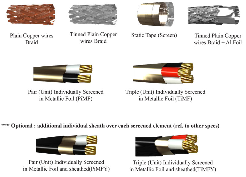
5 ) Screening of cabling elements
When screening of individual cable elements is specified (or in relevant sectional specification ) , it shall be selected from those listed one or any combination of the following :
5-1 ) a plain or coated metal braid
5-2 ) a combination of a foil, and a plain or coated metal braid .
The use of a drain wire is optional when this type of screen is applied;
5-3 ) a foil applied with a minimum overlap of 20 % and with a drain wire in direct contact with the metallic side of the foil.
If a drain wire is incorporated it shall be in contact with the main screen element. The drain wire is either solid or stranded made of plain or metal coated copper wire.
Care should be taken when putting dissimilar metals in contact with each other. Coatings or other methods of protection may be necessary to prevent galvanic interaction.
|
 |
|
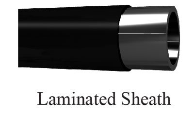
6 ) Screening of the cable core
The cable core shall be protected with a protective layer , when it is covered with a screen. When screening of the cable core is specified, it shall be selected from those listed in above section . Screening over the cable core may also be in the form of a laminated sheath .
|
|
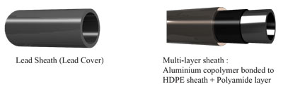
7 ) Chemical and /or environmental protection
When chemical or environmental protection is required, one of the following methods shall be used.
7-1 ) Lead Sheath
7-2) Multi layer sheath (comprise a laminated sheath and an additional layer of polyamide)
|
|
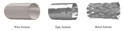
8 ) Metallic protection
When required by the relevant sectional specification the armouring shall consist of one or more of the following:
8-1) layer of round or flat galvanised steel wires;
8-2) single or a double layer of steel or brass tapes;
8-3) galvanized steel or tinned copper wire braid.
|
|
9 ) Outer sheathing
The outer sheathing material shall be appropriate to the operating environment and may be selected from the materials listed below :
a) PVC EN 50290-2-22
b) Polyethylene EN 50290-2-24
c) Halogen free F.R EN 50290-2-27
10 ) Fauna proofing (Anti-Termite and/or Anti-Rodent)
The relevant sectional specification shall indicate details of the fauna proofing required to protect the cable against attack by fauna (such as rodents or termite).
The protection may be a choice of armouring , special wrapping tape ,a choice of outer sheath material or any combination of these.
|